The gate of plastic mould refers to a short and thin runner connecting flow path and the strong performance, and is the entrance of the resin into the cavity. The shape, number, size and location of the gate in the mold will have a great impact on the quality of the plastic parts. So the selection of gate is one of the key points of plastic mold design. There are many types of gate in injection molding such as direct spruce gate, side gate, fan gate, etc. In this article, you’ll learn 9 popular injection molding gate types with descriptions in detail and you will learn some gate selection tips.
Injection Molding Classification Of Gate – 9 Popular Types Of Injection Molding Gate
Gate design is important thing to consider when designing a mold. Take a look at the 9 different types of plastic injection molding gate and choose the right for your mold design.
1. Direct Spruce Gate
When placing the gate directly to the base of the molded product residual screen tent to occur because the injection pressure will directly apply to the molded product, but its’ mold instruction is most simple.
2. Side Gate
The side gate is also called edge gate, which is generally set on the parting surface and feeds from the outer side of the cavity . The side gate is a typical rectangular cross-section gate, which can easily adjust the shear rate and gate closing time during mold filling, so it is also called standard gate.
The characteristics of side gate are simple gate section shape, convenient processing, precise processing of gate size, flexible selection of gate location, so as to improve the filling condition, no need to unload the mold from the injection molding machine can be corrected. The gate removal is convenient and the trace is small. The side gate is especially suitable for two plate multi cavity mould.
3. Flash Gate
This type will be applied to the plate shaped molded product, this type is effective to prevent deformation by suppressing residual string.
4. Disc Gate
Disc gates are used for cylindrical plastic parts with large inner holes, or plastic parts with large square inner holes. The gate is on the periphery of the entire inner hole. The plastic melt enters the mold cavity at approximately the same speed from the periphery of the inner hole, the plastic part will not produce weld lines, the stress of the core is uniform, and the air is removed in order.
5. Ring Gate
The ring gate is arranged on the outside concentric with the cylindrical cavity, that is, the gate is arranged around the cavity, so it can be called an outer ring-shaped gate, and its gate position corresponds to the inner disc gate. Suitable for thin-walled long-pipe plastic parts.
Because the melt of the plastic part evenly enters the cavity around the core, the mold filling is uniform, the exhaust effect is good, and the plastic part has no welding marks. However, it is difficult to remove the gate and leave obvious gate marks on the outside of the plastic part. Ring gates are mostly used for small, multi-cavity molds.
6. Tab Gate
This is a method that set up a tab on the side of the molded product and place a gate. Normally, the gate and the tab should be placed at a right angle gate sale will happen on the gate part, so suppressing residual stream and flow marks inside the tent is possible.
7. Overlap Gate
The overlap gate is also called a lap gate, which is basically the same as the side gate, but the gate is not on the side of the cavity, but on one side of the cavity. It is a typical impact gate, which can effectively prevent the jet flow of plastic melt. If the forming conditions are improper, surface pits will be generated at the gate. It is difficult to cut off the gate, which will leave obvious gate marks on the surface of the plastic part.
8. Fan Gate
The fan gate is a gate that gradually expands and is a variant of the side gate. It is commonly used to form plate-shaped plastic parts with a larger width. The gate gradually widens along the feed direction, and the thickness gradually decreases to the thinnest. The plastic melt is evenly distributed in the width direction, which can reduce the internal stress of the plastic parts and reduce the warpage deformation. The cavity has a good exhaust volume and avoids surrounding air. However, it is difficult to remove the gate and the trace is obvious.
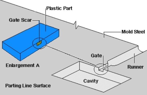
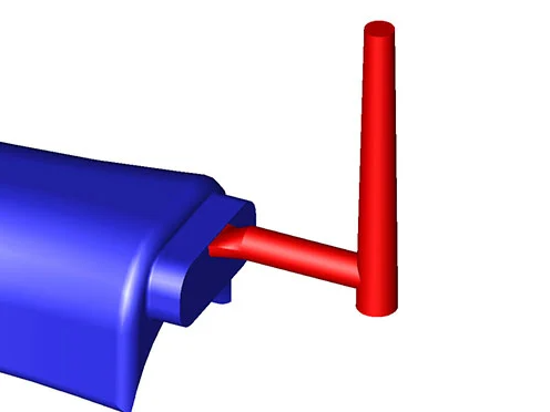
9. Tunnel / Submarine Gate
Tunnel gates are machined below the parting line so that as the part is ejected the gate will be trimmed automatically. This style of gate is common for injection molding for small parts, high cavitation molds, or where gates need to be trimmed automatically. The limitation of edge gates is the maximum cross-sectional area. Having too large of a tunnel gate can cause cracking or undesirable cosmetic issues due to the automatic shearing. Due to the size limitation attempting to fill a large part with a small gate may also cause excessive shear heating and fill problems.
Injection Molding Gate Location Selection
The location and number of injection mold gates often determine the appearance quality and performance of the product, so when choosing the location and number of gates, the following points should be followed:
1. The gate should be set at a position that can fill all corners of the cavity at the same time.
2. The plastic injected into the cavity should maintain a uniform and stable flow rate at all stages of the injection molding process.
3. The gate should be set in the thicker wall of the product, so that the melt flows from the thick section to the thin section to facilitate the replenishment and ensure the complete filling of the mold.
4. The choice of gate location should minimize the plastic filling process to reduce pressure loss.
5. The location of the gate should be selected in a position that is beneficial to the removal of gas in the cavity.
6. The gate should not make the molten material directly punch into the cavity, otherwise it will produce a swirling flow, leaving a swirling trace on the plastic parts, especially narrow gates are more prone to this defect.
7. Consideration should be given to the possible occurrence of weld marks, bubbles, depressions, virtual positions, insufficient glue injection and spraying.
8. The location of the injection mold gate should be selected at the position that can avoid fusion lines on the surface of the product. When the occurrence of fusion lines cannot be avoided, the location of the gate should be selected considering whether the location of the fusion lines is suitable.
9. The setting of the gate should avoid the phenomenon of melt fracture.
10. When the projected area of the product is large, avoid opening a gate on one side to prevent uneven stress on the injection
11. The gate of injection molding should be set at a position that does not affect the appearance of the product
12. Do not set gates in the parts of the product that bear bending load or impact load. Generally, the strength near the gate of the product is the worst;
13. The gate position of the injection mold with a slender core should be far away from the molding core, so that the molding core is not deformed by the material flow.
14. When forming large or flat plastic parts, double gates can be used to prevent warpage, deformation and lack of material.
15. The operation of the water removal port should be made as easy as possible, preferably automatic operation.S