How to making anything moldable? in this guide, we are focusing primarily on that effort where you may have gone through some 3D printed prototypes or may have had a design that you’ve done on some small scale, but all the sudden your demand has risen, now you need to make this into a scalable moldable product. so let’s go through a few design examples and talk about injection molding in general, why it’s so specialized, and why it is so design-dependent as well.
Injection Molding Principles – Understand the Process To Understand The Results
The biggest thing is to understand. know what will happen and when it’ll happen, so that you can be informed about the whole process. every tool is cut and every tool is designed to your part. everything is custom-made, it’s not just your part, it’s also to a specific material. with the thousands of materials, it essentially could have several different options in your tool requirements. the part of the tools cut process is when the tool opens and closes, you’ll have the molten plastic that gets injected in there with high pressure. material limitation dictates a lot of that, the part itself is injected quickly, but then it has to cool quickly at the same time. otherwise, that part can’t get ejected without causing damage to the part. when that party jacks, it usually falls onto a box or maybe falls in a conveyor belt. every part would be a little bit different how they get removed. there are no real limitations to parts geometry itself. a lot of the features that are not captured in that direction of pull are creating undercuts those are created. using slides or sometimes hand-loaded, cores help capture those features on the part itself.
How Injection Molding Works
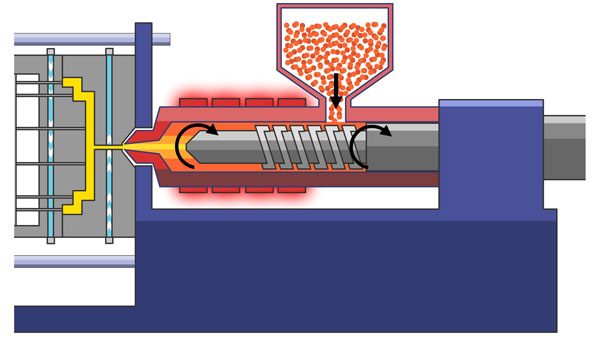
The hopper at the top is where putting the plastic material, goes in there in that pellet form, it’s fed to the hopper at the beginning of the number two which is the barrel and the screw. there’s a screw rotating and turning, as it goes along, it’ll be heated up at the same time. the bumps at the very top are heaters. they heat the material as it turned plasticizers into the actual material itself. as it is brought up to the front, which is where the tool is injected into the core, the cavity side of the tool to help fill the part. it’s injected into the tool, then once it cools, it usually will drop into a bin or the conveyor.
From the time the material goes into the machine to the time the part hits the barrel, it could usually be a few minutes, but it could range from 30 seconds to 2 minutes. it depends on the part geometry and material of the part. there’s a lot of key factors that they play into that cycle time.
The Three Most Common CAD “Evaluate” Tools
When we talk about design for manufacturability, a lot of that is around plastic, how to mitigate some of these costs including undercuts, uniformity, and drafts. this will help with all of your designs, it applies to every single injection molding design out there. any part you can buy off-the-shelf, any part you’ll see in a car, all of the three analyses apply to that. the first one is thickness analysis, undercut analysis, and draft analysis. we identify the overall mobility of the part. undercuts is a feature that is perpendicular to the parting line or the direction of draw. either a hand-loaded core or side actions are needed to form those features because they’re not captured in the direction of the draw. so we do encourage you to evaluate that your design eliminates any if unnecessary because they do add some cost to the part, you want to make it most cost-effective.